Table Of Content

V4 Quick Guide

V4 Functions P1

V4 Functions 2

V3 Segments

V3 Mesh Def.

V3 Placements

V3 Quick Start
![[2 A] Generic Meshes On Spline Blueprint ../images/architecture/0023/v2-generic/thumbs/01.jpg](../images/architecture/0023/v2-generic/thumbs/01.jpg)
V2 Generic BP
![[2 B] Generic Spline Blueprint Examples ../images/architecture/0023/v2-examples/thumbs/01.jpg](../images/architecture/0023/v2-examples/thumbs/01.jpg)
V2 Examples
![[1] Railings Clone Blueprint Documentation ../images/architecture/0023/v1/thumbs/01.jpg](../images/architecture/0023/v1/thumbs/01.jpg)
V1 Railings Fences

Ver History
V3 - Spline Placement Nodes
These nodes place the defined mesh on the selected spline segment.

Content:
Introduction
The Spline Placement node uses the Mesh On Spline definition to place the meshes on the selected Spline Segment.
Placement nodes have to be connected with the white pin to the construction node.
You can either chain them up in one row where one Placement node is connected to the next one. Or you can use the Sequence node to arrange them in multiple rows.

A list of available Placement Nodes will appear. Try the Spline Placement A Auto if you're unsure which one to use.
Below is an explanation of what each node does.

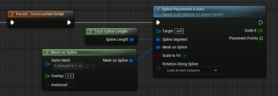
Spline Placement A Auto
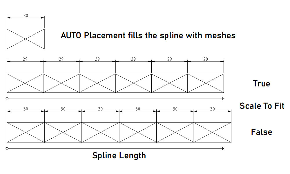
This option uses the size of the mesh to fill the entire spline segment with as many meshes as fit.
Setting Scale to Fit to true will scale the meshes to fit exactly on the spline length.
Setting Scale to Fit to false will not scale the meshes and they won't exactly fit the spline length.
Check the calculated size with a variable connected to its Distance output pin.
| Input Pins | |
| Target | Leave this connection empty |
| Spline Segment | Connect a spline segment node here. |
| Mesh On Spline | Connect a mesh definition node here. |
| Scale To Fit | Tick this box to scale the mesh slightly so it fills the entire spline segment length. |
| Rotation Along Spline | This defines the rotation of the mesh when
the spline is bended. - Look At Next Instance: aligns the mesh even with curved splines - Spline Rotation: uses the spline rotation at spawn point of the mesh - Default Rotation: No mesh rotation will be applied along the spline |
| Output Pins | |
| Placecments | An array holding all the placement transforms. Use this to place poles with the pole placement. |
| Calculated Distance | The actual distance between two mesh instances on the spline. |
| Scale X | The scale of the mesh in spline direction. Will be 1.0 unless 'Scale to Fit' is ticked. |
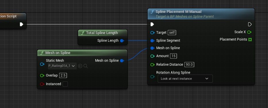
Spline Placement M Manual
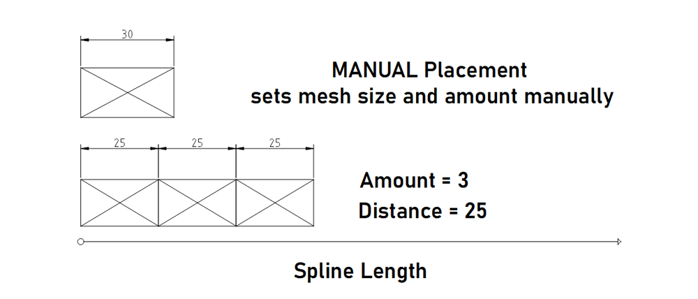
This manually sets both the size of the mesh and how many of them are placed on the spline. The amount is limited by the length of the spline.
| Input Pins | |
| Target | Leave this connection empty |
| Spline Segment | Connect a spline segment node here. |
| Mesh On Spline | Connect a mesh definition node here. |
| Amount | How many meshes should be placed at most. They need to fit on the length of the spline |
| Relative Distance | Distance between spawn points. The mesh will be scaled if the value is not 0.0 |
| Rotation Along Spline | This defines the rotation of the mesh when
the spline is bended. - Look At Next Instance: aligns the mesh even with curved splines - Spline Rotation: uses the spline rotation at spawn point of the mesh - Default Rotation: No mesh rotation will be applied along the spline |
| Output Pins | |
| Scale X | The scale of the mesh in spline direction. Will be 1.0 unless 'Scale to Fit' is ticked. |
| Placments | An array holding all the placement transforms. Use this to place poles with the pole placement. |
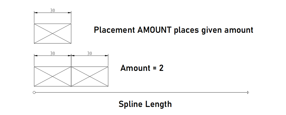
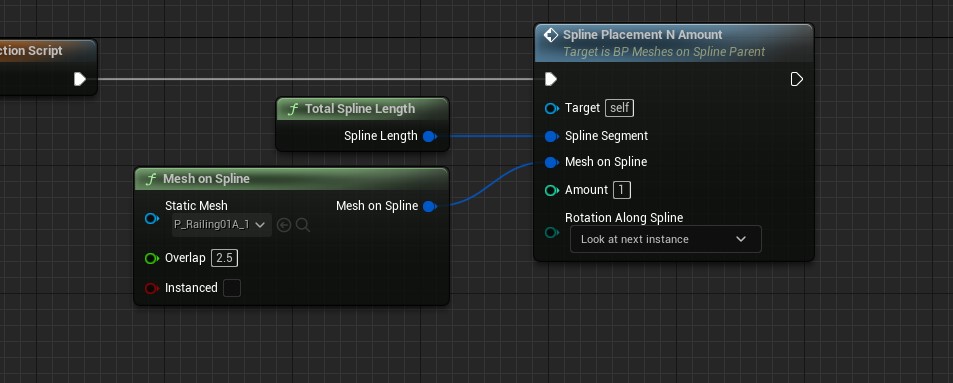
Spline Placement N Amount
This will place the number of meshes given with default scale. Use this placement for the Spline Segment A N or N A
| Input Pins | |
| Target | Leave this connection empty |
| Spline Segment | Connect a spline segment node here. |
| Mesh On Spline | Connect a mesh definition node here. |
| Amount | How many meshes should be placed at most. They need to fit on the length of the spline |
| Rotation Along Spline | This defines the rotation of the mesh when
the spline is bended. - Look At Next Instance: aligns the mesh even with curved splines - Spline Rotation: uses the spline rotation at spawn point of the mesh - Default Rotation: No mesh rotation will be applied along the spline |
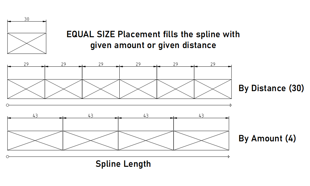
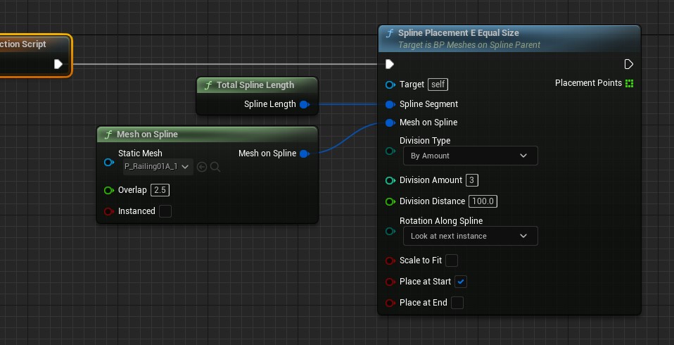
Spline Placement E Equal Size
Places either the Amount or uses the Division Distance given to fill the spline segment.
This works well for free standing poles or bollards or similar objects.
Use the Spline Placement P Poles when the poles are seperated but a part of a railing.
| Input Pins | |
| Target | Leave this connection empty |
| Spline Segment | Connect a spline segment node here. |
| Mesh On Spline | Connect a mesh definition node here. |
| Division Type | - By Amount: places the Amount of
meshes - By Division Size: places meshes by the given Division Distance from each other |
| Amount | How many meshes should be placed |
| Division Distance | Distance between spawn points |
| Rotation Along Spline | This defines the rotation of the mesh when
the spline is bended. - Look At Next Instance: aligns the mesh even with curved splines - Spline Rotation: uses the spline rotation at spawn point of the mesh - Default Rotation: No mesh rotation will be applied along the spline |
| Scale to Fit | when ticked: scales the Division Distance slightly to fill the spline |
| Place at Start | weather a mesh is placed at the start of the spline (0.0) |
| Place at End | weather a mesh will be placed at the very end of the spline |
| Output Pins | |
| Placments | An array holding all the placement transforms. Use this to place poles with the pole placement. |
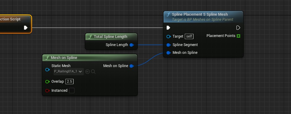
Spline Placement S Spline Mesh
This placement will place Spline Meshes. This is a special variation of meshes that can follow the spline closely. Like a winding pipe. The mesh needs to have sub divisions to be able to bend.
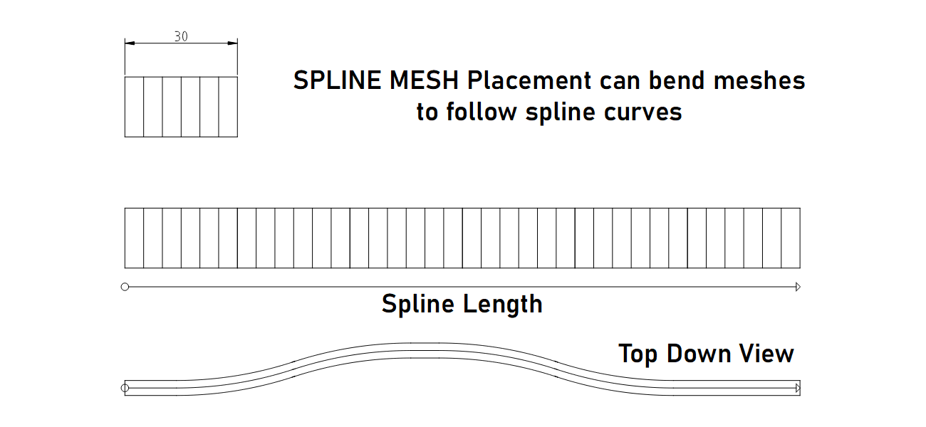
The spline mesh will always be auto scaled to fit best over the entire length of the spline.
- The mesh needs to point into the X direction of your modeling software and be originated at 0.0.0.
- Nanite may have to be disabled for this type of meshes.
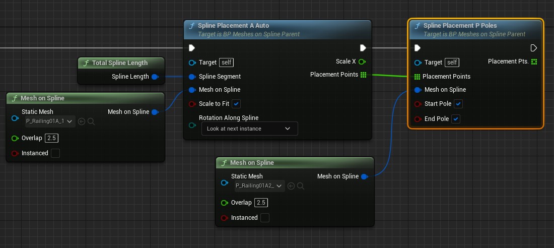
Spline Placement P Poles
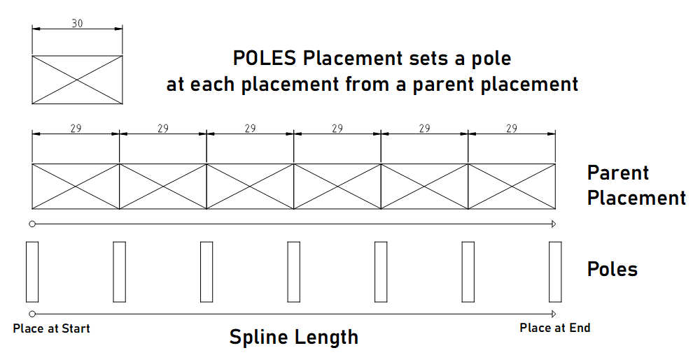
Uses the placement points from another placement. This is meant for pole meshes that are placed between railing meshes. Rotation Along Spline is fixed to the spline rotation.
Use one of the other placements to place free standing bollards or light poles.
| Input Pins | |
| Target | Leave this connection empty |
| Placement Points | Connect the Placement Points output from another placement here. |
| Mesh On Spline | Connect a mesh definition node here. |
| Start Pole | A mesh will be placed at the start of the spline segment |
| End Pole | A mesh will be placed at the end of the spline segment |
| Output Pins | |
| Placment Pts | An array holding all the placement transforms. |
Spline Placement Lights
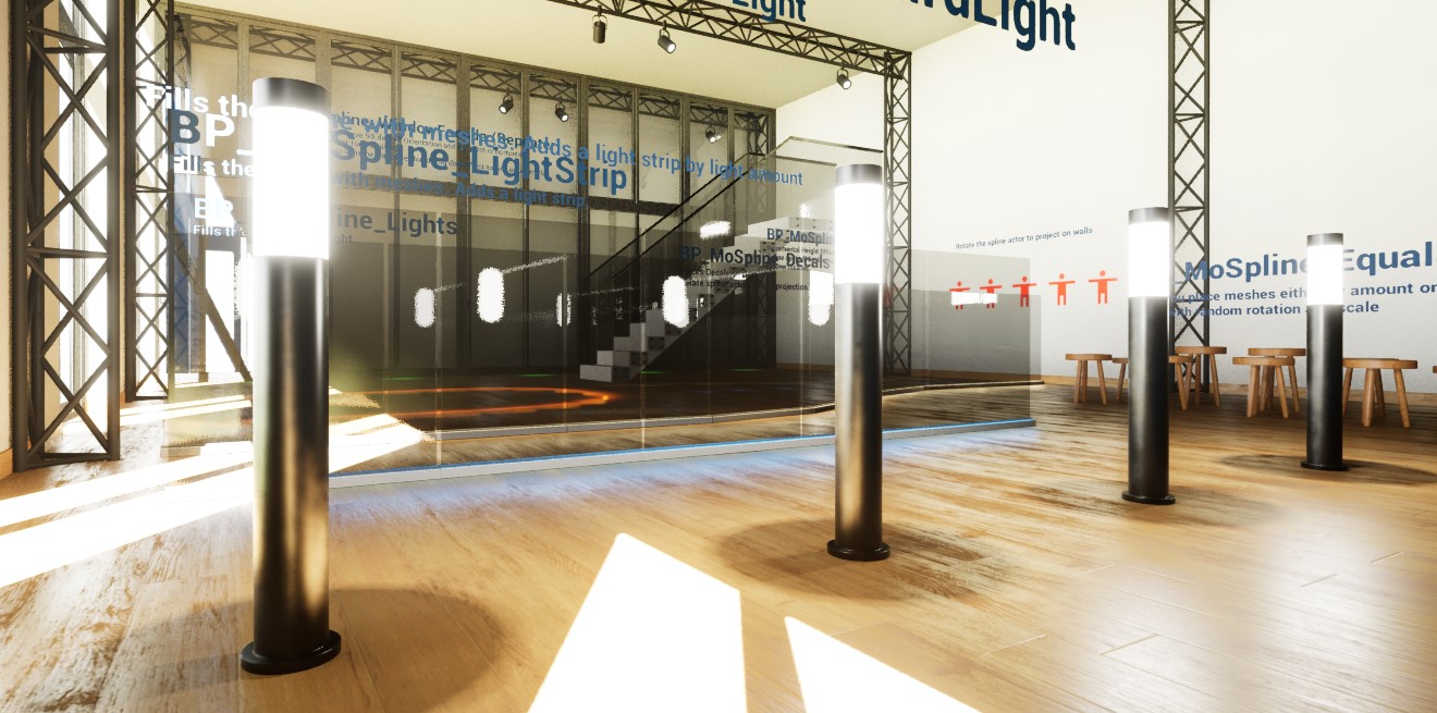
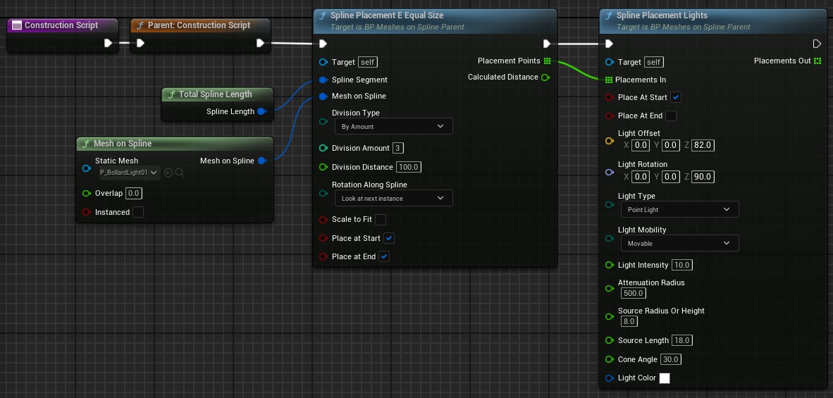
Lights can be placed using the Placement Points output pin. They can then be rotated and offset relative to the placement points.There may be some limitations with the lights. This image is in version 5.0. The radius of the light source is set so it extends over the glass. There should be no shadow on the floor from the bollard mesh.
| Input Pins | |
| Placements in | Get a Placement Points array from another placement |
| Light at Start | Place a light at the first placement |
| Light at End | Place a light at the end |
| Light Offset | Add a relative offset from the placement |
| Light Rotation | Set the rotation of the light |
| Light Type | Choose what type of light should be placed |
| Light Mobility | Static and Stationary lights can be baked. Mobile light is dynamic and best for Lumen |
| Light Intensity | The intensity of the light |
| Attenuation Radius | How far the light should have an effect |
| Source Radius or Height | The radius for spot and point lights. The height for rectangle lights |
| Source length | The length of the light |
| Cone Angle | The angle of the cone of a spot light |
| Light Color | Choose what color the light should have |
| Output Pins | |
| Placement Out | passes through the placement points |
Spline Placement Decals
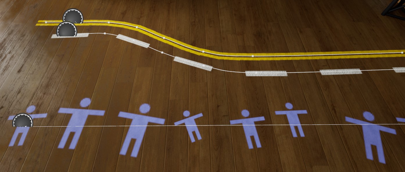
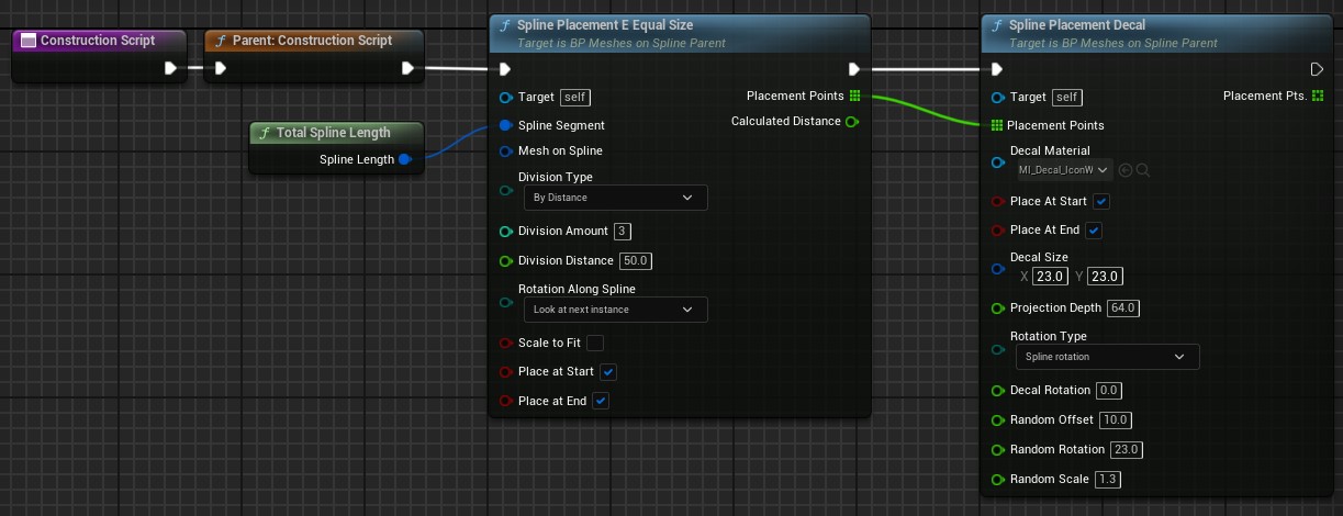
Decals can be placed with the Spline Placement Decals in conjunction with the Placement E Equal Size or any other placement.You'll have to use the output pin of another placement to place decals. Leave the Mesh On Spline pin empty if there is no mesh to be placed.
Random placement values can be updated by clicking on the Create Random Stream tick box in the details panel of the blueprint.
| Input Pins | |
| Placement Points | Get a <i>Placement Points</i> array from another placement |
| Decal Material | Use a valid decal material. Needs to be in the <i>Defered Decals</i> domain and has the blending mode <i>Translucent</i> |
| Place at Start | Place a light at the first placement |
| Place at End | Place a light at the end |
| Decal Size | The size in units |
| Projection Depth | How far in Z direction the decal should project. Keep low to avoid unnecessary projections |
| Rotation Type | Rotation relative to spline |
| Decal Rotation | Additional rotation of the decal projection |
| Random Offset | A max random +/- offset. 0.0 means no random offset |
| Random Rotation | A max random rotation left or right. 0.0 means no random rotation |
| Random Scale | Scales the decal randomly if > 1.0. A value of 1.3 scales from 0.7 to 1.3 randomly. |
| Output Pins | |
| Placement Pts | passes through the placement points |
 Top of page