Table Of Content

V4 Quick Guide

V4 Functions P1

V4 Functions 2

V3 Segments

V3 Mesh Def.

V3 Placements

V3 Quick Start
![[2 A] Generic Meshes On Spline Blueprint ../images/architecture/0023/v2-generic/thumbs/01.jpg](../images/architecture/0023/v2-generic/thumbs/01.jpg)
V2 Generic BP
![[2 B] Generic Spline Blueprint Examples ../images/architecture/0023/v2-examples/thumbs/01.jpg](../images/architecture/0023/v2-examples/thumbs/01.jpg)
V2 Examples
![[1] Railings Clone Blueprint Documentation ../images/architecture/0023/v1/thumbs/01.jpg](../images/architecture/0023/v1/thumbs/01.jpg)
V1 Railings Fences

Ver History
V4 - Spline Tools Function Library - Part 1
BPL-SDotSplineTools contains the functions needed to create the blueprints in this project. The functions can be used in any blueprint within a project were the library is present.
Part 1 covers the essentials and Placement Nodes.
Content:
SplineTools_Railings / Bluerpints / Etc
The library doesn't need to be opened or modified.

Create a New Spline Blueprint
- Click the [+ Add] button in the content browser
- Select Blueprint Class
- Select Actor
Name the new blueprint

Add a Spline Component
- Click [+ Add] to add a new component to the blueprint
- Start typing Spline
- Click on Spline to add the new spline component

Blueprint parts
The blueprint needs to have at least one set of these parts:- Placement Node - how many meshes will be placed on the spline
- Spline Segment - which part of the spline the mesh will be placed (next page)
- Spline Mesh - how each of the mesh will be placed and with which material (next page)

This example has a different railing mesh with an additional pole at the end.
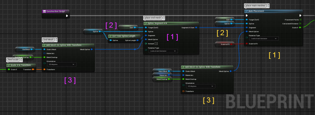
Placement Nodes
Placement Nodes tell the blueprint how and where to place the spline meshes on the spline.- Click on the white Exec or flow pin. Hold the mouse button while moving the mouse to the side.
- Start typing placement until the name of the placement appears
- Click on the placement name from the list

Placement nodes need to be connected to the purple Construction Script or another white Exec pin.
- Drag the Spline Component from the component list into the scene
- Connect the spline component variable to the Spline pin
- Connect a Spline Segment to the Segment pin. The Get Total Spline Length function node will give the entire spline length.
- Connect a Reference to Self node to the Target (Self) pin
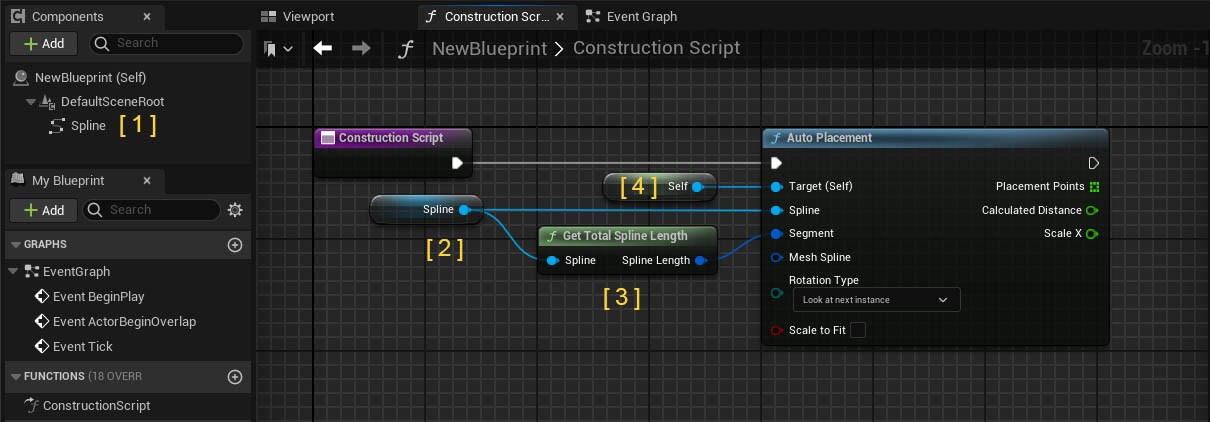
Auto Placement
| Mesh | The Mesh to be placed |
| Materials | The Materials to overwrite what is set in the mesh editor |
| Mesh Overlap | + 1.0 will overlap two mesh placements by 1
unit - 1.0 will leave a gap of 1 unit |
| Orientation | Initial rotation of the mesh. Use to correct meshes facing sideways |
| Transform | Offset, Rotation, Scale of the meshes |
| Scale To Fit | The mesh will be scaled to fit the entire spline length |
| Rotation Type | How to line up the meshes along the spline |
| Calculated Distance | [ Info ] Displays the current scale or distance between placement points |
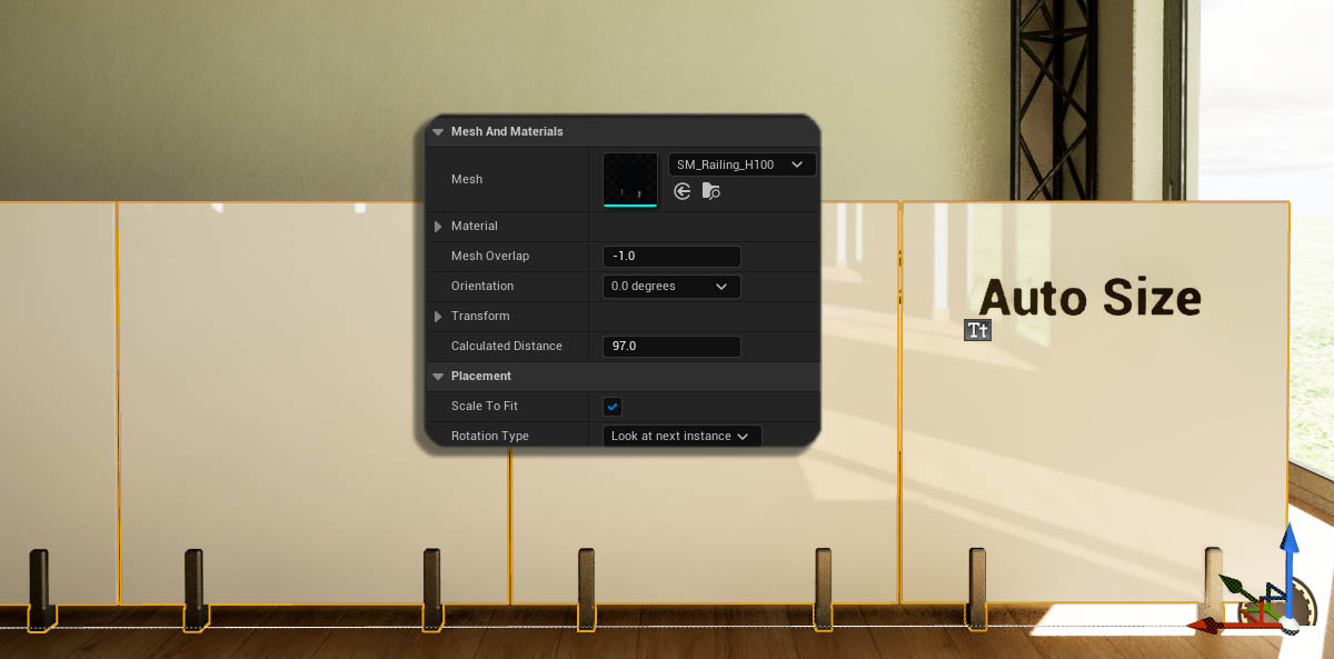
Mesh Placement Nodes
Equal Size Placement
| Division Type | Division calculated by Amount or Mesh Size? |
| Division Amount | Amount of meshes if Type is set to amount |
| Division Size | Distance between placement points if Type is By Distance |
| Scale To Fit | Distance will be scaled to cover the entire spline length |
| Place at Start / End | Place mesh at first / last position |
Manual Placement
Places an amount of meshes in a given distance from each other
Pole Placement
Uses the Placements Points Array from another placement node. Useful for placing Pole meshes.

Placement / Segment Combo Nodes
Technically these nodes are Segment Nodes. They also have a placement componentSpline Segment A N
This node places N meshes at the end of the spline segment and outputs the rest of the spline as Segment A Start to be used by another placement.Spline Segment N A
This node places N meshes at the start of the spline segment and outputs the rest of the spline as Segment A End to be used by another placement.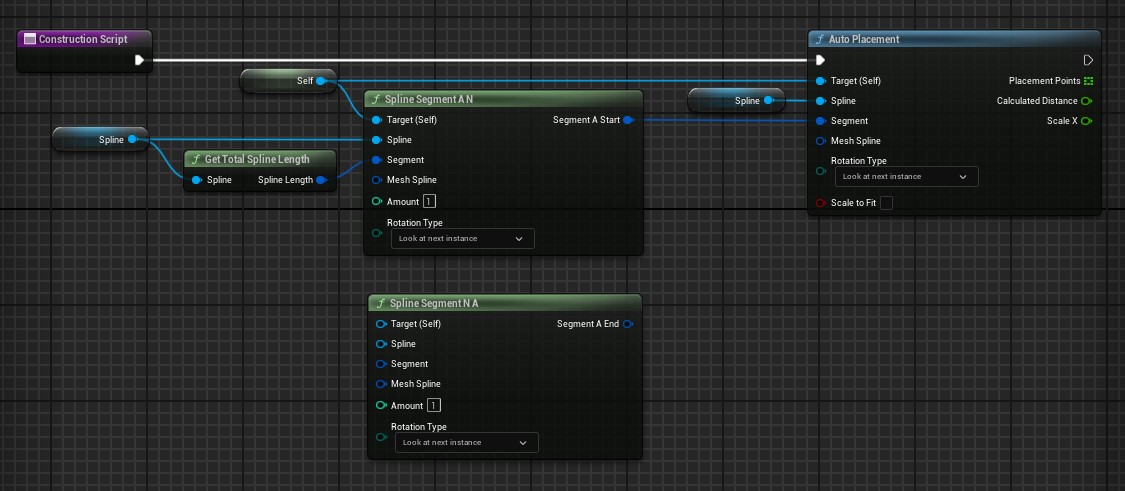
Spline Mesh Placement
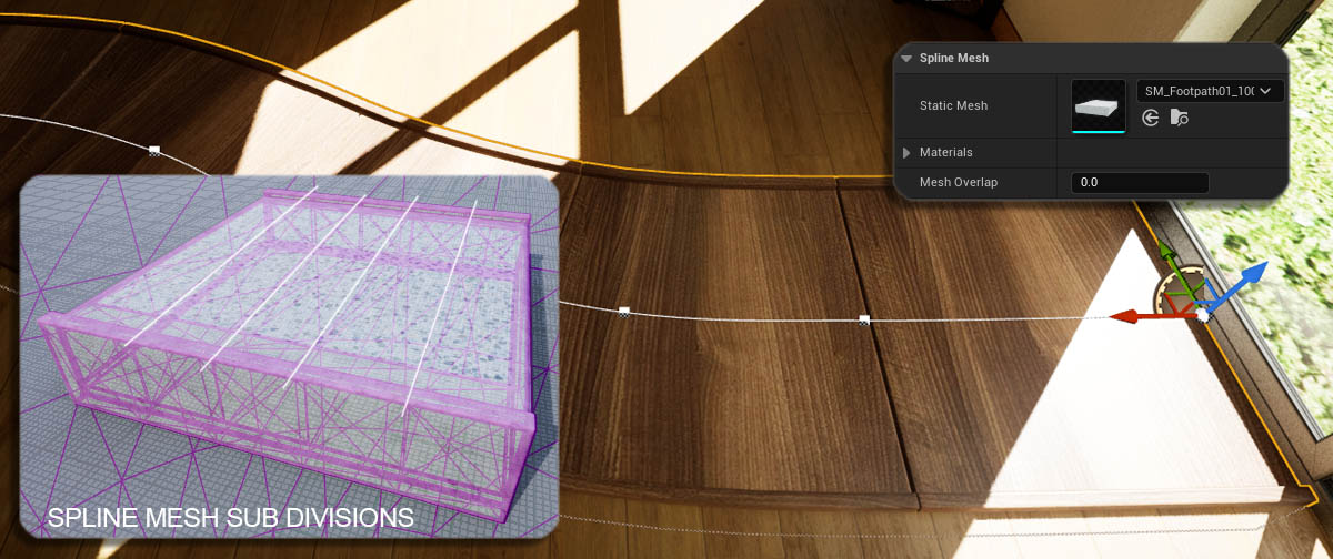
Places spline meshes onto the spline, like a continuous pathway.
Meshes need to have subdivisions where they can be bended. Keep the subdivisions equal in size.
Overlap will work like a scale as spline mesh placements do not overlap or leave a gap.
Placement Points Array
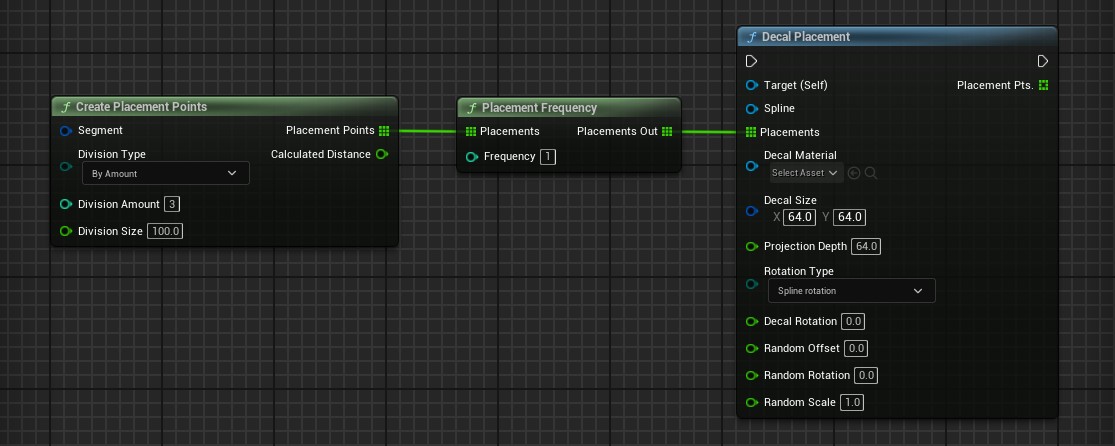
Some Placement nodes require a Placement array from another node. Or the placement arrray can be created with these nodes.Create Placement Points
Creates placement points similar to the Equal Size Placement
Placement Frequency
Reduces the number of points entered on the left side.
A Frequency of 2 will output every other point. A Frequency of 3 will remove the 1st and 2nd point and only output every third placement point.
Light Placement
Adds an additional light to each mesh module. It uses the placement array of another placement node for positioning the lights.| Placements | This placement type uses the Placement Points Array from another placement |
| Light Type | Select the type of light |
| Light Transform | The relative transform for the lights |
| Intensity | Light Intensity in unreal light units |
| Light Color Attenuation Radius |
Color and radius of the light |
| Cone Angle | Outer cone angle of spot lights |
| Rectangle Size | 2D vector of rectangle light's size |

Decal Placement
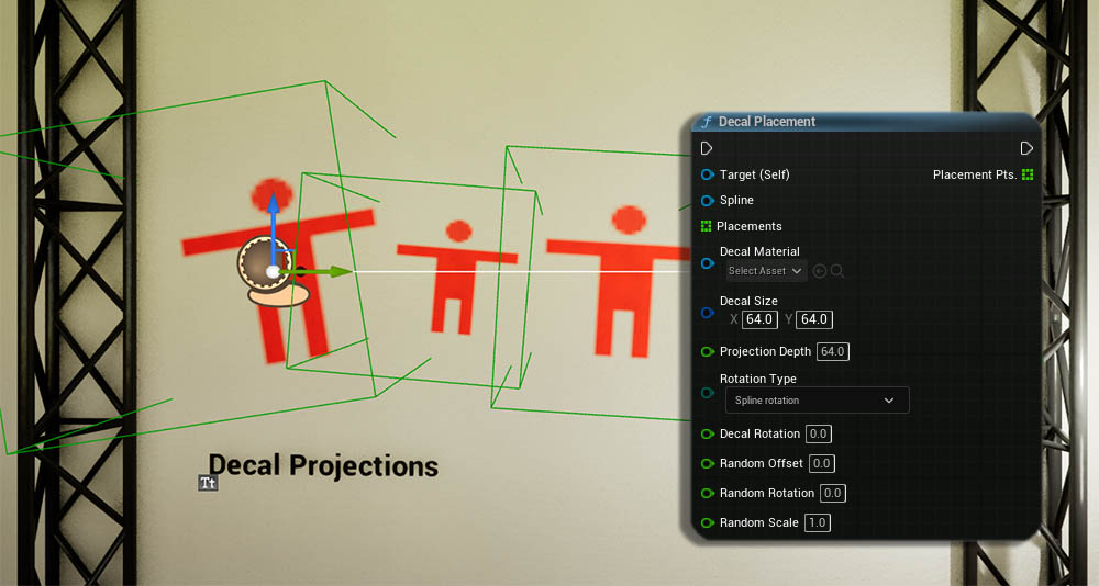
Allows to place decals along a spline. Decals project textures on objects in the scene. This placement uses the Placement Array of another placement for positioning.The decal may project to the wrong side of the mesh if it seems to be black when it shouldn't be.
| Placements | This placement type uses the Placement Points Array from another placement |
| Decal Material | a decal material that can be used with a decal actor |
| Decal Size | the size of the decal projection |
| Projection Depth | How far the decal actor projects |
| Decal Rotation | The initial rotation of the projection |
| Random Offset/Rotation | a value 10.0 will rotate or offset the decal by a random value between -10 to +10 |
| Random Scale | scaling of 1.1 will use a random value between 0.9 and 1.1 |
Decals haven't change much over the engine version. You should be able to use the documentation for any version of Unreal.
 Top of page
 Decals - Unreal Engine Documentation